
Storage Tank VOC Emissions — Sources, Mechanisms and the Control Hierarchy
A practical framework for understanding where tank emissions originate and which control layer should address them.
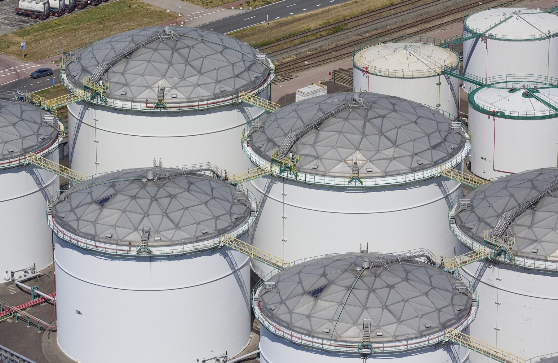
Storage-tank emissions are often treated as a single problem with a single technical answer. They are not. Different losses arise from different physical mechanisms: vapour-space breathing and displacement in fixed-roof tanks; rim-seal, deck-fitting and seam losses in floating-roof tanks; roof landings; and operational events such as filling, emptying, pigging, cleaning and maintenance.
The engineering task is therefore to connect the emission mechanism to the control measure. The most robust sequence is to reduce vapour generation at the source, contain the vapour that remains, recover or treat residual vapour where necessary, and then maintain and verify the installed controls throughout their service life.
1. Where emissions come from
Evaporation begins when a volatile liquid is exposed to a vapour space in which the vapour partial pressure is below equilibrium. The quantity released depends on product volatility, temperature, exposed liquid area, vapour-space volume, tank geometry, atmospheric conditions and the way the tank is operated.
For fixed-roof tanks, the principal routine mechanisms are standing losses and working losses. Standing losses are associated with vapour-space expansion and contraction as temperature and pressure change. Working losses occur when incoming liquid displaces vapour from the tank. Flashing can add a separate source where the entering liquid releases dissolved or entrained light components because pressure or temperature conditions change.
Floating roofs reduce the active vapour space by placing a barrier close to the liquid surface. Remaining losses are associated mainly with the rim seal, deck fittings, mechanically joined deck seams, wetted shell surfaces and non-routine events such as roof landings. The relative importance of those sources depends on roof type, condition and operation.
2. The control hierarchy
A useful control hierarchy prevents the common mistake of selecting equipment before understanding what is actually driving the emissions.
| Stage | Objective | Typical measures |
|---|---|---|
| 1. Reduce generation | Reduce exposed liquid surface and unnecessary vapour generation | Tank selection, floating roof, temperature and operating controls |
| 2. Contain | Close the remaining vapour paths | Rim seals, deck-fitting controls, tight seams, pressure/vacuum management |
| 3. Capture or treat | Deal with residual vapour that cannot reasonably be prevented | Vapour balance, recovery, adsorption, condensation, oxidation |
| 4. Maintain and verify | Keep real performance aligned with intended performance | Inspection, gap measurement, OGI, testing, recalculation and RBI |
3. Tank configuration comes first
The first design question is whether the tank configuration is appropriate for the stored product and service. True vapour pressure, storage temperature, throughput, filling and emptying rates, product compatibility and upset scenarios all matter. A tank that is fundamentally mismatched to its service cannot be made efficient simply by adding accessories.
Internal floating roofs may be full-contact or non-contact designs. External floating roofs are directly exposed to wind and weather. Covered external floating roofs and domed tanks create another operating environment. These configurations do not have identical emission pathways, so comparison should be based on mechanisms and actual design details rather than labels.
4. Details can dominate performance
For floating roofs, high performance depends on the whole vapour barrier. A well-designed deck combined with poor rim sealing, open gauge-pole paths or damaged fittings can still emit significantly. Nominal rim space alone is not enough: shell roundness, verticality, local deformation, roof eccentricity, seal travel and product deposits can all affect whether the seal remains effective.
Deck seams on internal floating roofs require the same practical thinking. Laboratory loss factors are useful inputs, but field performance depends on whether the installed joint can repeatedly achieve and retain the tested condition over long seam lengths and years of operation.
5. A dome is part of a system
An aluminium dome can provide weather protection and can convert an exposed external floating roof into a covered configuration. This may reduce wind influence and improve the operating environment for seals and equipment. A dome is not automatically an emission-control system by itself. The outcome depends on the floating roof or other vapour-control system below it and on how the enclosed vapour space is vented or controlled.
6. Calculation, inspection and measurement belong together
EPA AP-42 Chapter 7.1 and API MPMS Chapter 19 provide widely used methods for estimating storage-tank evaporative losses. They are essential for inventories, permitting, screening and comparison. Their output remains a model result: it is only as representative as the input data and equipment assumptions.
The strongest approach combines calculation with physical verification. Calculate the expected loss profile, inspect the equipment that the calculation assumes is present and functioning, use measurement or OGI where it adds information, and recalculate when product, operation or equipment changes.
7. Lifecycle performance
Emission controls age. Elastomers change, fabrics wear, seals gap, fittings are damaged or left open, vents foul and tanks settle or distort. The efficiency assumed at design stage is therefore not automatically the efficiency delivered in year ten.
Emission management should include a performance interval as well as a structural inspection interval. The right interval follows from degradation rate, consequence, detectability, service history and confidence in the previous inspection—not simply from the passage of calendar time.
8. Practical sequence for a terminal
- Define products, operating envelope and tank configuration.
- Identify every significant emission path and operational event.
- Build a transparent baseline estimate with stated assumptions.
- Inspect the actual condition of the installed emission controls.
- Identify legal, permit and BAT expectations.
- Compare technically feasible control measures and their interactions.
- Evaluate reduction potential, safety, integrity, operability and lifecycle cost.
- Implement the selected measures and verify the resulting performance.
References and technical basis
- US EPA — AP-42 Chapter 7.1, Organic Liquid Storage Tanks (final revision October 2024)
- US EPA — TANKS Emissions Estimation Software, Version 5 (TANKS 5.3 released July 2026)
- EEMUA 213 — Emission reduction from oil storage tanks and loading operations
- European Commission JRC — Emissions from Storage (EFS) BREF, formally adopted July 2006
Standards and regulations change. Confirm the edition, legal applicability and permit conditions for the tank, product and jurisdiction before design or compliance decisions are made.