
Internal Floating Roofs, Rim Seals and Deck Fittings — How the Main Tank-Side Controls Work
A neutral engineering guide to the three control layers that determine most floating-roof tank emission performance.
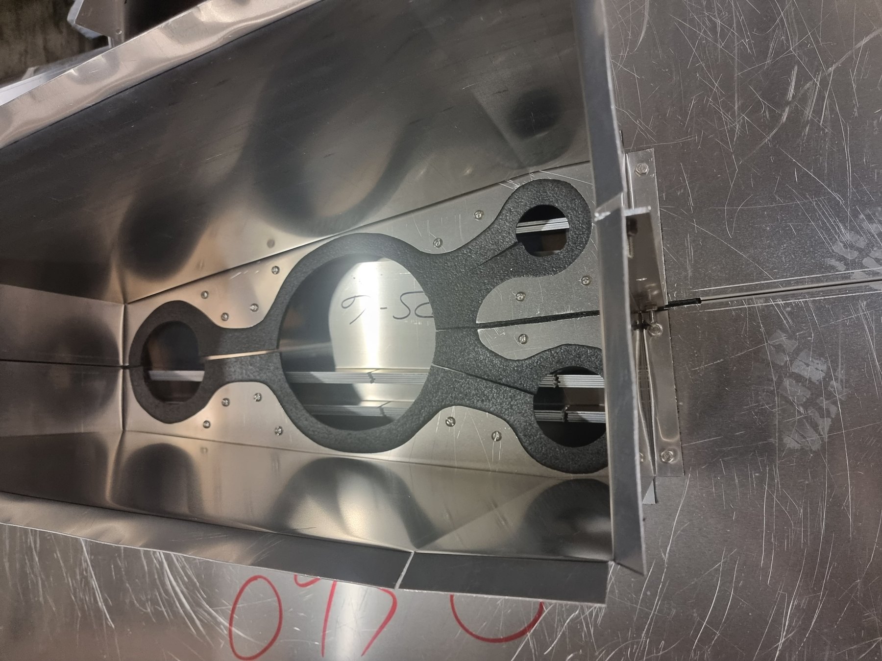
An internal floating roof is not one emission-control device. It is a system consisting of a deck, a perimeter seal and a set of penetrations and fittings. The overall performance is determined by the combined vapour paths, not by the headline efficiency of one component.
This paper explains the main mechanisms without ranking suppliers or proprietary products. The objective is to show which design and inspection questions matter when comparing configurations.
1. What an internal floating roof changes
A fixed-roof tank without an internal floating roof has a vapour space over most of the liquid surface. An IFR moves with the liquid level and reduces the exposed liquid area and active vapour volume. The remaining emissions are concentrated at the perimeter, deck seams, fittings and non-routine operating events.
Internal floating roofs are commonly grouped as full-contact and non-contact designs. Full-contact roofs support most of the deck directly on the liquid through buoyant panels or modules. Non-contact roofs typically use pontoons to support a thin deck above the liquid. The geometry of the residual vapour space is therefore different.
2. Full-contact does not mean zero emission
Even a deck that is predominantly in contact with the liquid still has panel joints, penetrations, the rim space and local areas that may not be in contact. The important design question is how much exposed liquid or connected vapour space remains and how reliably those paths are sealed.
A meaningful comparison therefore considers the entire deck layout rather than the nominal classification alone.
3. Non-contact roofs control a connected vapour space
A skin-and-pontoon roof creates a vapour space beneath much of the deck. Once this space approaches equilibrium with the liquid, evaporation is limited, but any route that allows saturated vapour to escape is connected to a comparatively large underlying area. Deck seams and fittings therefore need to be evaluated as part of the full vapour-barrier system.
The benefit of the design is not determined by seam type alone. Pontoon layout, deck tension, penetrations, rim geometry, buoyancy and maintainability also matter.
4. Rim seals
The annular space between floating roof and shell must remain sealed while the roof moves through a tank that is never perfectly cylindrical. Mechanical shoe seals, liquid- or foam-filled seals and flexible wiper arrangements use different mechanisms to follow this movement. Primary and secondary seals may be combined where regulation, service or performance requires it.
The seal should be evaluated against the actual operating envelope: nominal and extreme rim spaces, shell roundness, verticality, welds and obstructions, roof eccentricity, product residue, friction, roof movement and material compatibility. A seal that performs well at one nominal gap may fail to maintain contact elsewhere in the tank.
5. Deck fittings
Columns, gauge poles, stilling wells, sample wells, support legs, ladders and vents penetrate the deck or require movement relative to it. Each penetration is a potential vapour path. Good design minimises the open area, maintains a seal through the operating movement and allows the component to be inspected.
A single poorly controlled slotted gauge pole or open well can undermine the performance of an otherwise good roof. Fittings therefore deserve the same design attention as the perimeter seal.
6. Deck seams
Mechanically joined IFRs contain substantial lengths of seam. API MPMS Chapter 19 includes deck-seam loss factors and separate test methods for establishing loss factors for internal floating-roof seams. These values are useful for emission estimation, but the field joint must reproduce and retain the condition represented by the test.
Seam design should be assessed for sealing principle, assembly tolerance, dependence on field-applied sealant, mechanical movement, inspectability, material compatibility and repairability. The strongest paper certificate has limited value if the construction method cannot reliably reproduce the tested configuration over the full tank.
7. Buoyancy, structure and emissions interact
Buoyancy and structural design are not separate from emission performance. Excessive deflection can change seam behaviour and fitting clearances; an overloaded perimeter can affect roof level and seal contact; an insufficient operating envelope can cause sticking or damage. The roof must remain stable and operable under the loading and flow cases relevant to the tank.
The current edition of API 650 should be used for project requirements, supplemented by the owner’s integrity standard and applicable local regulation.
8. What to inspect
- Rim-seal gaps, damage, attachment and material condition.
- Deck seams, fasteners, gaskets and visible evidence of vapour or liquid paths.
- Gauge poles, columns, wells, legs and other penetrations for open areas and damaged seals.
- Roof level, local distortion, buoyancy concerns and evidence of interference.
- Vent function and any modifications that changed the original flow path.
- Product deposits, corrosion or contamination that can change movement or sealing.
References and technical basis
- American Petroleum Institute — API 650 publication updates / current-edition notices
- American Petroleum Institute — Subcommittee on Evaporation Loss Estimation, MPMS Chapter 19
- US EPA — AP-42 Chapter 7.1, Organic Liquid Storage Tanks (final revision October 2024)
- EEMUA 213 — Emission reduction from oil storage tanks and loading operations
Standards and regulations change. Confirm the edition, legal applicability and permit conditions for the tank, product and jurisdiction before design or compliance decisions are made.