
Domes, Venting and Vapour Recovery — Matching the Measure to the Emission Mechanism
How domes, pressure/vacuum management and vapour recovery fit into a complete emission-control system.
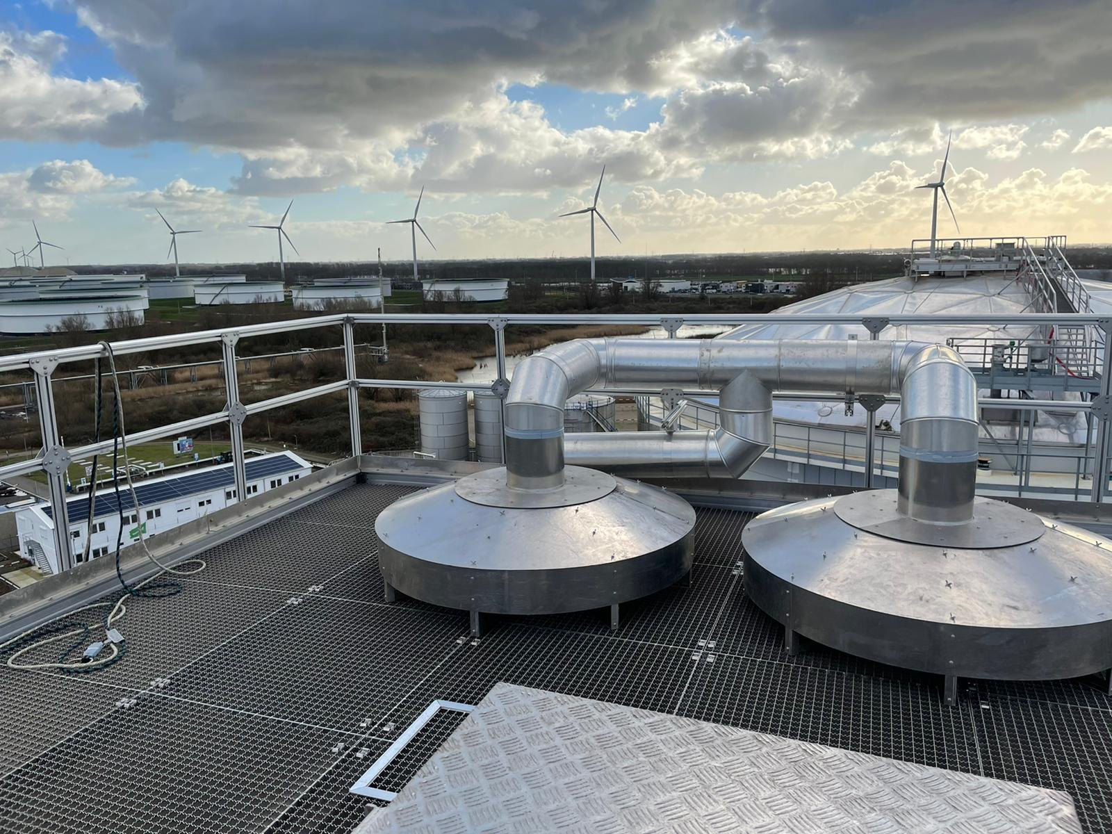
Domes, vents and vapour-recovery systems are often discussed together because each affects the tank vapour space. Their functions are fundamentally different. A dome provides a fixed cover and operating environment. Venting protects the tank against pressure and vacuum outside its allowable range. Vapour recovery or treatment deals with vapour that is intentionally captured.
Good emission-control design keeps those functions distinct and then engineers their interfaces.
1. Aluminium geodesic domes
An aluminium geodesic dome is a lightweight self-supporting fixed cover. It can protect the tank contents and floating roof from rain, wind and debris, eliminate the need for columns through the tank interior and provide a covered operating environment for an external floating roof.
For a covered external floating roof, reducing direct wind exposure can reduce some wind-driven loss mechanisms and reduce weather-related deterioration. The actual emission performance still depends on the floating roof, rim seals, deck fittings and the way the space beneath the dome is ventilated. The dome should therefore be treated as part of the tank configuration, not as a stand-alone percentage reduction.
2. Dome design still begins with structural engineering
Emission benefits do not override the primary structural requirements. The dome has to withstand the applicable dead, live, wind, snow, thermal and other project loads; transfer forces into the tank safely; accommodate support movement where applicable; remain watertight to the specified acceptance criteria; and provide safe access.
Panel sealing, supports, fasteners, structural members, manufacturing tolerances and constructability all influence long-term reliability. These choices should be assessed against the applicable code rather than vendor-specific design rhetoric.
3. Normal venting
Liquid movement and temperature changes alter the tank vapour volume. Normal venting must allow inbreathing and outbreathing without exceeding the allowable pressure or vacuum. A vent that is made more restrictive in an attempt to reduce emissions can create a structural hazard if the tank pressure envelope is not checked.
API 2000 is the principal API standard for venting atmospheric and low-pressure storage tanks; API’s standards plan lists the 8th edition dated August 2026. The project should use the current applicable edition and evaluate both normal and emergency cases.
4. Pressure/vacuum valves as an emission measure
On fixed-roof tanks, appropriately selected P/V settings can reduce unnecessary breathing to atmosphere compared with open vents. The setting is constrained by tank design pressure, vacuum capability, blanketing system, connected equipment and operational transients. Leakage and seat condition also matter; a nominal set pressure is not the same as tight in-service performance.
Inspection and maintenance of vent devices therefore belong inside the emission-management programme.
5. Vapour balance and closed vent systems
Vapour balancing transfers displaced vapour to another vessel or system rather than releasing it directly. Closed vent systems route vapour to recovery or abatement. Both require a continuous, adequately sized and sufficiently tight capture path.
The design must consider normal and peak flow, vapour composition, condensation, liquid carry-over, fire and explosion protection, pressure drop, equipment availability and what happens when the recovery system is unavailable.
6. Recovery and treatment options
| Technique | What it does | Key selection variables |
|---|---|---|
| Condensation | Cools/compresses vapour so part of it returns to liquid | Vapour concentration, temperature, pressure, recovery value |
| Adsorption | Captures VOCs on a solid medium for regeneration or disposal | Composition, humidity, cycle time, breakthrough |
| Absorption | Transfers VOCs into a liquid solvent or product stream | Solubility, solvent management, downstream recovery |
| Membrane separation | Separates hydrocarbon-rich and lean streams | Pressure, composition, turndown, polishing requirement |
| Thermal/catalytic oxidation | Destroys VOC rather than recovering it | Concentration, fuel demand, heat integration, destruction requirement |
7. The system boundary is the important part
A terminal may install an efficient vapour unit and still emit through tank vents, open hatches, poor seals or bypasses. Conversely, a well-contained tank can overload a vapour system if peak flow cases were underestimated. The complete path from liquid surface to final outlet has to be assessed as one system.
Commissioning should therefore verify not only individual equipment operation but also capture, pressure behaviour, alarm and bypass logic, and the condition of the tank-side interfaces.
8. Selection logic
Use a dome where the fixed-cover function and covered floating-roof configuration solve a defined problem. Use P/V management where the tank can safely operate within a controlled pressure range. Use recovery or treatment where residual captured vapour remains material or regulation requires it. Combining measures is often more effective than expecting one device to solve every emission mechanism.
References and technical basis
- American Petroleum Institute — API 650 publication updates / current-edition notices
- American Petroleum Institute — Standards Plan (including API 2000 current-edition information)
- EEMUA 213 — Emission reduction from oil storage tanks and loading operations
- US EPA — AP-42 Chapter 7.1, Organic Liquid Storage Tanks (final revision October 2024)
- European Commission JRC — Emissions from Storage (EFS) BREF, formally adopted July 2006
Standards and regulations change. Confirm the edition, legal applicability and permit conditions for the tank, product and jurisdiction before design or compliance decisions are made.