
IFR Buoyancy, Structural Loads and Testability
Buoyancy is not simply the gross volume of a floating-roof panel multiplied by liquid density. The effective displaced volume, roof weight, non-contact areas, damaged compartments and load cases all affect margin. The source…
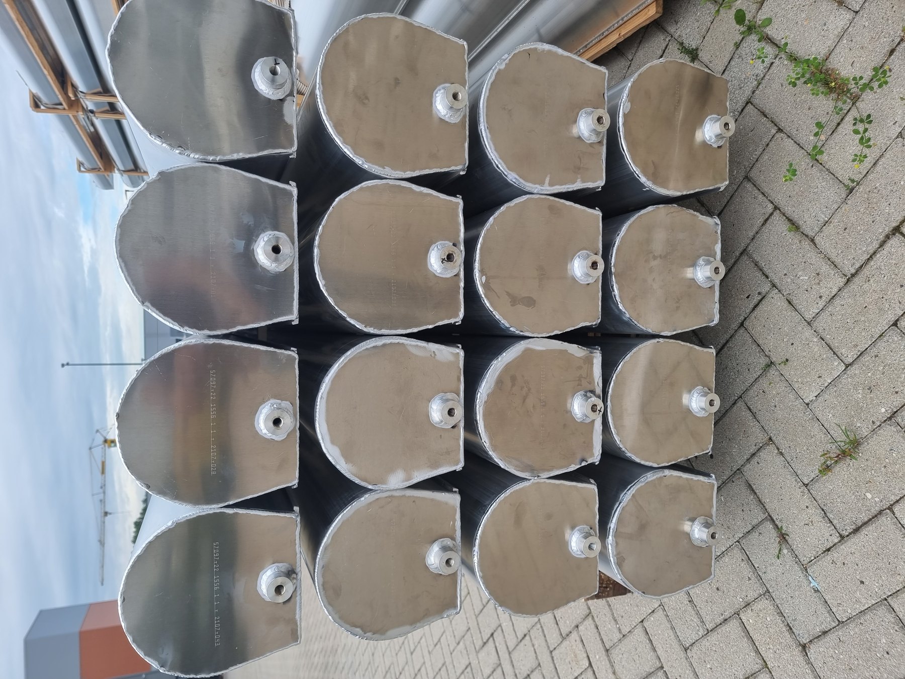
A practical framework for reviewing whether a floating roof can remain buoyant, intact and verifiable
Buoyancy is not simply the gross volume of a floating-roof panel multiplied by liquid density. The effective displaced volume, roof weight, non-contact areas, damaged compartments and load cases all affect margin. The source evaluation also highlights a related issue: if compartments or joints cannot be tested, the owner has limited means to confirm that the assumed buoyancy remains available. A robust IFR review should connect calculation, compartment design, structural load path and testability.
Key points
- Use effective displaced volume, not idealized external geometry, when assessing buoyancy.
- Non-contact areas and structural elements may reduce available displacement.
- Buoyancy margin should be evaluated together with credible flooded-compartment scenarios and concentrated loads.
- Legs, clips, battens and appurtenance beams must transfer local loads without progressive failure.
- Test ports and testable joints improve confidence that the as-built roof matches the calculation.
Buoyancy is a system property
The roof floats because the mass of displaced liquid balances roof weight and imposed loads. The practical margin depends on which parts of the roof actually displace liquid. A design with significant dry or non-contact zones can have less effective buoyant volume than a calculation based on overall panel dimensions suggests.
From theoretical to actual displacement
The HFC evaluation in the source set recalculates buoyancy after accounting for panel geometry and separate auxiliary floaters and obtains a materially lower margin than the supplier’s theoretical figure. The exact numbers are project-specific, but the lesson is general: confirm the volume that can physically displace product and identify which volume remains available after a compartment is lost.
Structural load path
Floating condition produces distributed upward force; maintenance and access create local downward loads. Connections between panels, battens, girders, appurtenance beams and support legs must transfer both. A roof can have sufficient global buoyancy yet still be vulnerable to local clip or joint failure if the load path is weak.
Testability and inspection
The source material repeatedly values pressure-tested compartments and inspection/test ports. Where a buoyant module has no test connection, it may be difficult to confirm leak tightness during manufacture or after years in service. Testability does not eliminate failure, but it turns an assumption into a condition that can be checked.
Floatation testing
The archived engineering letter discusses floatation testing under historical API and EN requirements and notes that, for some roof types, commissioning during the initial product fill may be an accepted route while other constructions may require a water floatation test. That distinction must be verified against the current project code basis before use. Water testing also introduces practical questions such as water quality, corrosion sensitivity, disposal and maximum exposure duration.
Review questions for purchasers
- What exact volume is counted as buoyant and how was it derived from the production geometry?
- What damaged-compartment or flooded-module cases are included?
- How are concentrated deck loads transferred near legs and appurtenances?
- Can every buoyant compartment and critical seam be tested?
- How will buoyancy be re-verified after repair or at a future inspection?
Conclusion
A good buoyancy calculation is necessary but incomplete. Confidence comes from matching the calculation to actual geometry, proving the structural load path and providing practical means to test the components on which buoyancy depends. The roof should be designed not only to float on day one, but to remain verifiably fit for service.
Source basis and publication notes
This draft is a supplier-neutral synthesis of the project source material. Supplier-specific claims, branding and proprietary conclusions have been removed or reframed as general engineering considerations. No attempt has been made in this draft to update historical standards or regulatory references beyond what the source material itself states.
Principal source material
- Evaluation Aluminator HFC.docx
- Whitepapers.zip — IFR’s and floatation test requirements 20170125 UK rev 1.docx
- Product Selection and Design Guide HMT.docx (floating roof design criteria)
- Whitepapers.zip — Hidden Considerations for Aluminum IFR Design REV121015.pdf
Before publication: verify current editions and clause references for API, EEMUA, EN, NFPA, PGS and applicable local regulation; confirm any quantitative design limits against the project-specific code basis; and use project photographs only after branding/confidentiality review.