
Tank Geometry, Rim Space and Floating-Roof Seal Performance
Floating-roof seals are flexible, but not infinitely flexible. Tank roundness, verticality, settlement, shell buckles and roof eccentricity change the rim space that the seal must bridge. The project sources show that a tank…
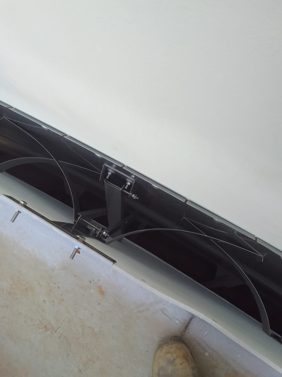
Why roundness, verticality and roof position can determine both operability and emissions
Floating-roof seals are flexible, but not infinitely flexible. Tank roundness, verticality, settlement, shell buckles and roof eccentricity change the rim space that the seal must bridge. The project sources show that a tank can remain within structural acceptance criteria while presenting a rim-space envelope that challenges an IFR or seal design. Seal selection should therefore be based on measured geometry across the operating height, not on nominal tank diameter alone.
Key points
- Nominal rim gap is not the same as operating rim-space envelope.
- Out-of-roundness, verticality and roof eccentricity can combine rather than occur separately.
- A seal’s working range must be checked against the tank’s actual geometry and foreseeable degradation.
- Membrane length, contact height and liquid immersion affect emission performance as rim space changes.
- The floating roof can become the limiting component even when the tank shell remains structurally acceptable.
Geometry is an operating variable
Atmospheric tanks are thin-shell structures. Fabrication tolerance, settlement and local deformation mean that the shell is never a perfect cylinder. The IFR paper notes that the relevant dimension for a floating roof is the horizontal shape at each liquid level — the plane through which the roof must travel.
Why bottom measurements are insufficient
A diameter measured near the tank bottom cannot by itself demonstrate that the roof has adequate clearance at all elevations. Verticality, local shell deformation and settlement can move the shell centreline or change local radius as the roof rises. A survey intended for seal or IFR design should therefore capture the operating envelope, not only one reference elevation.
Rim space and seal range
Seal mechanisms have minimum and maximum positions. At small rim gaps, components can buckle, bind or generate excessive force; at large gaps, contact pressure, membrane overlap or shoe geometry may become inadequate. The source evaluation of a specific IFR design illustrates how a narrow working range can make the roof sensitive to tank deviations even when the shell itself is within broader tank-code tolerances.
Seal geometry and emissions
The seal comparison material identifies contact length and membrane length as important performance variables. A seal that keeps a long, stable contact surface and enough flexible membrane to follow lateral roof movement is more likely to maintain sealing under variable rim space. Conversely, a rigid or short membrane can open gaps as the roof moves off centre.
Survey and selection workflow
- Obtain rim-space measurements around the full circumference at representative roof elevations.
- Review shell verticality, settlement and local buckles or weld protrusions.
- Separate roof eccentricity from shell out-of-roundness by comparing opposing measurements.
- Build a minimum-to-maximum rim-space envelope including credible future degradation.
- Compare this envelope with the mechanical working range of both primary and secondary seals.
- Check appurtenance clearances and the IFR structure at the same extreme positions.
Lifecycle implication
Geometry can change over time. Settlement, repairs, jacking, shell distortion and product-temperature cycles can alter the relationship between roof and shell. The geometry basis should therefore be retained as part of the integrity file and revisited when a seal shows abnormal wear, gaps or local over-compression.
Conclusion
A floating-roof seal is a mechanism operating inside a moving geometric envelope. Good performance comes from matching that mechanism to the real tank, including tolerances and degradation. This makes geometry survey data a core input to emission-control design and inspection planning.
Source basis and publication notes
This draft is a supplier-neutral synthesis of the project source material. Supplier-specific claims, branding and proprietary conclusions have been removed or reframed as general engineering considerations. No attempt has been made in this draft to update historical standards or regulatory references beyond what the source material itself states.
Principal source material
- Whitepapers.zip — IFR’s and tank out of roundness 20090515 UK rev 0.docx
- Product Selection and Design Guide HMT.docx (rim-space survey and seal design sections)
- Whitepapers.zip — seal comparison.docx
- Evaluation Aluminator HFC.docx
Before publication: verify current editions and clause references for API, EEMUA, EN, NFPA, PGS and applicable local regulation; confirm any quantitative design limits against the project-specific code basis; and use project photographs only after branding/confidentiality review.