
Tank Venting — The Interface Between Emission Control and Safe Operation
Venting is sometimes discussed as if it were only an emission pathway. The project source material shows the opposite: venting is first a pressure- and atmosphere-management function that must remain compatible with the chosen…
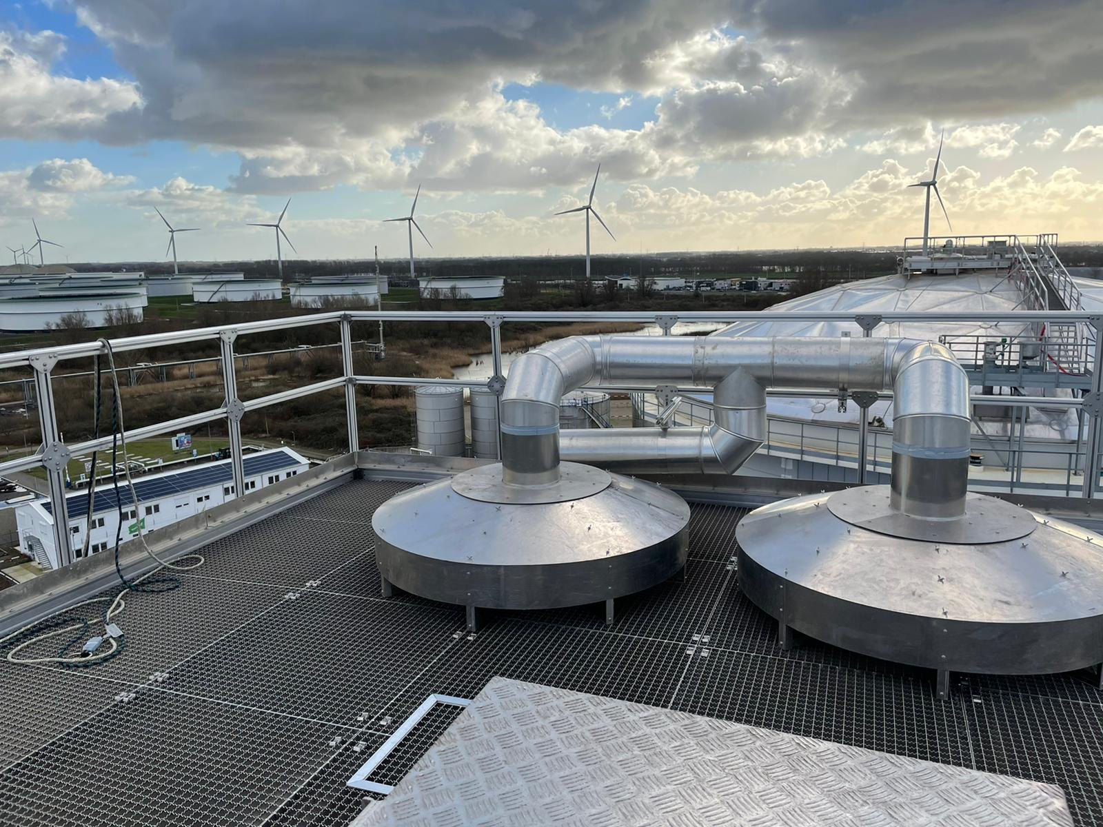
Circulation venting, normal breathing, operational gas flows and the consequences of restricting a tank
Venting is sometimes discussed as if it were only an emission pathway. The project source material shows the opposite: venting is first a pressure- and atmosphere-management function that must remain compatible with the chosen emission-control configuration. Aluminium domes over floating roofs, normal filling and emptying, temperature changes, nitrogen blanketing and abnormal gas slugs each create different design questions. Emission reduction measures should never compromise the tank’s ability to breathe safely.
Key points
- Separate circulation ventilation of the vapour space from pressure/vacuum vent sizing.
- A dome that is allowed to hold pressure can impose significant uplift on the tank shell and anchorage.
- Nitrogen blanketing changes safety and operating behaviour, but also introduces consumption and displacement flows.
- Filling, emptying and thermal breathing should be reviewed with the actual tank and product data.
- Operational events such as pigging can create transient gas flows far above normal breathing rates.
Venting is not one function
The sources distinguish several mechanisms that are often mixed together: circulation ventilation above an IFR, pressure/vacuum breathing caused by product movement and temperature change, and transient gas release from operational events. A robust design identifies each mechanism and assigns an appropriate flow path.
Free-vented dome configurations
Historical dome guidance in the source archive describes free-vented arrangements using openings at the perimeter together with an apex vent. The stated purpose is to dilute hydrocarbon vapour in the space above the IFR. The exact area and configuration are code- and project-dependent and should be verified against the current governing standard before publication or design use.
Normal breathing review
The separate venting paper calculates required capacity from tank filling and emptying conditions and uses conservative flow coefficients for labyrinth-type vents. This reinforces a broader design principle: the number and size of vents should be based on required flow capacity and pressure drop, not only on nominal nozzle diameter.
Pressure-holding domes and uplift
If the dome and tank are changed from a freely vented atmospheric arrangement to one that retains pressure, even a small pressure acting over the roof area can create large vertical forces. The dome-to-shell connection, top angle, shell and anchorage therefore have to be checked as one structural system. A pressure-capable dome should not be specified by changing the vent only.
Nitrogen blanketing
The archive notes two distinct reasons for nitrogen: preventing a combustible atmosphere and protecting oxygen-sensitive products. It also notes the operational consequence that nitrogen is displaced during filling and must be replenished as the tank empties. The emission and economic effect therefore depends on how the displaced gas is managed and whether vapour recovery or treatment is provided.
Transient operations
Pigging, vessel stripping and gas slugs can introduce gas at rates that bear little relation to normal tank breathing. The filling/pigging source material treats these as dedicated design cases requiring diffusers, pressure-relief paths through or around the IFR, and interlocks or restricted release lines where appropriate.
Inspection and maintenance
A vent that is correctly sized can still lose capacity through fouling, corrosion, bird screens, contamination or mechanical damage. Designs that permit direct inspection and cleaning without extensive disassembly improve the likelihood that the original capacity remains available over time.
Conclusion
Emission control and venting should be designed together. The tank must remain within its structural pressure limits and the vapour space must be managed for normal and abnormal operations. Once those safety functions are secured, the remaining vapour flow can be contained or treated in a controlled way.
Source basis and publication notes
This draft is a supplier-neutral synthesis of the project source material. Supplier-specific claims, branding and proprietary conclusions have been removed or reframed as general engineering considerations. No attempt has been made in this draft to update historical standards or regulatory references beyond what the source material itself states.
Principal source material
- Venting.docx
- Whitepapers.zip — Domes venting requirements 20160112 UK rev 2.docx
- Filling and Pigging2.docx
- IFR Nitrogen pigging 20160627 UK rev 1.docx
Before publication: verify current editions and clause references for API, EEMUA, EN, NFPA, PGS and applicable local regulation; confirm any quantitative design limits against the project-specific code basis; and use project photographs only after branding/confidentiality review.